General Assembly Area & Material
- A clean area to stage all of the material is required. The total area necessary to stage the material should be equal to the footprint area of the oven. It’s important that all of the components for your oven are stored in a clean, dry environment.
- Sub-Assembled items:
- Heater Box
- Recirculation ducts
- Transitions
- Doors
- Exhaust duct (if equipped)
- Control Panels
- Additional Recommended Equipment
- White chalk
- Temperature rated caulk
- Clamps
- Basic Hand Tools
- Ladders
- Welders
- Fork Trucks and/or overhead cranes
- Scissor lifts or boom-type lifts
- Lengths of steel to temporarily brace items during assembly
Oven Build Sequence
1. Clean the area of the floor where the oven is to be located, and mark where the location of the inverted structural steel uprights are to be located.
2. It’s recommended to lay out the structural pad placement (if equipped) and oven flashing layout with chalk lines.
3. Survey the area so that the uprights (if equipped) can be leveled (shims are included).
4. Set the uprights (if equipped) in place per the locations on the drawing, and lag the uprights to the concrete floor with included anchor bolts.
5. Once the uprights are installed, squared and parallel to each other, install the upper panel angle. This will lock the uprights in place and prepare you for the installation of panels.
6. Locate the insulated panel base flashing. Square the flashing by cross-measuring (tram) the assembly.
7. Lag the base flashing assembly to the floor. This is done by welding the supplied clip angle to the flashing and anchoring the clips to the plant floor with the supplied anchors. (If there are gaps between the flashing and the plant floor, the gaps should be filled with temperature-rated caulk.)
8. Install the wall panels. Start with a corner panel making sure that the corner panel is level in both orientations.
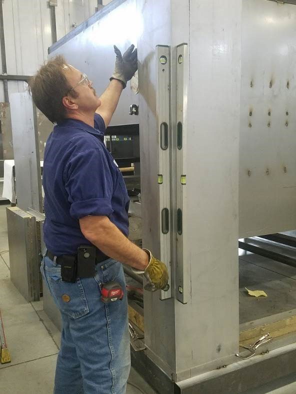
9. Tack weld temporary braces to the panel so that the panel doesn’t move.
10. Pack the male end of the panels with insulation. (A cutting template has been provided so that the insulation strips can be precut.)
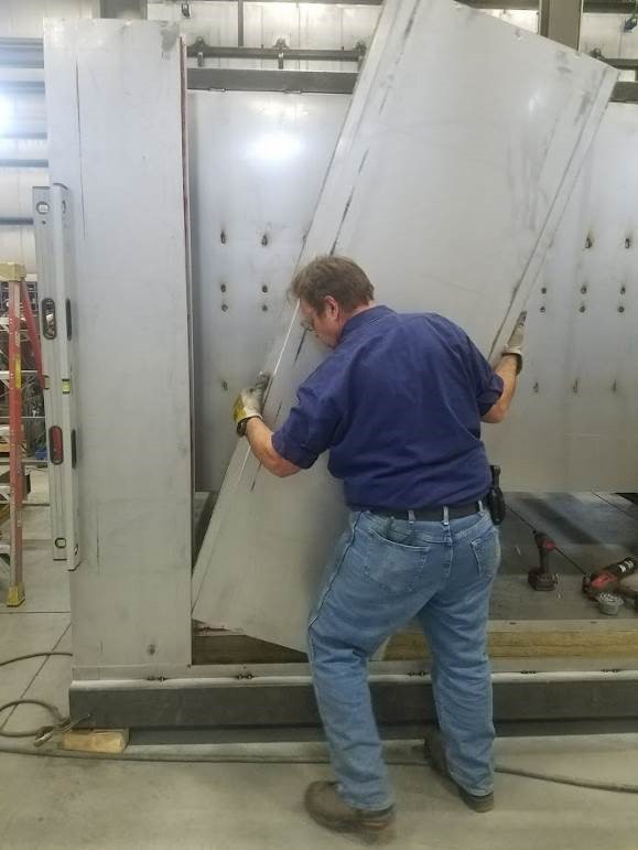
11. Insert the next wall panel into the corner panel. It is best to hold the next panel at a slight angle to the installed panel and start the male end of the new panel into the female opening of the installed panel. Then, straighten or level the new panel in place.
It is very important to maintain the correct panel gap. The insulated panel assembly drawing will show the “coverage” of each panel, which is the distance from female to female panel joints. When installed correctly, the gap, or reveal between the panels should be ¼’’ to 5/16’’.
12. As the wall panels are installed, TEK screws them in place with the base flashing so that their location does not change.
13. When you’re ready to install the door opening, it is also very important they are installed correctly.
- Be sure that the female joint is packed with insulation prior to inserting it into the door flashing.
- Cross-measure or trim the opening to verify the opening is “square” both before and after welding it in place.
- Weld the corner together.
14. Spot the chamber recirculation supply ducts in place.
15. Locate and tack weld the transition to the tops of the supply ducts.
16. Locate the chamber supply duct with their transitions to the drawing so that the top openings in the transition will align with the heater box plenum openings.
17. Mount the ducts in place by securing them to the structural steel uprights.
18. Locate and mount the return duct if equipped.
19. Assemble the heater box flashing in place.
20. Pack the top of the wall panels with insulation to the top of the panel angle.
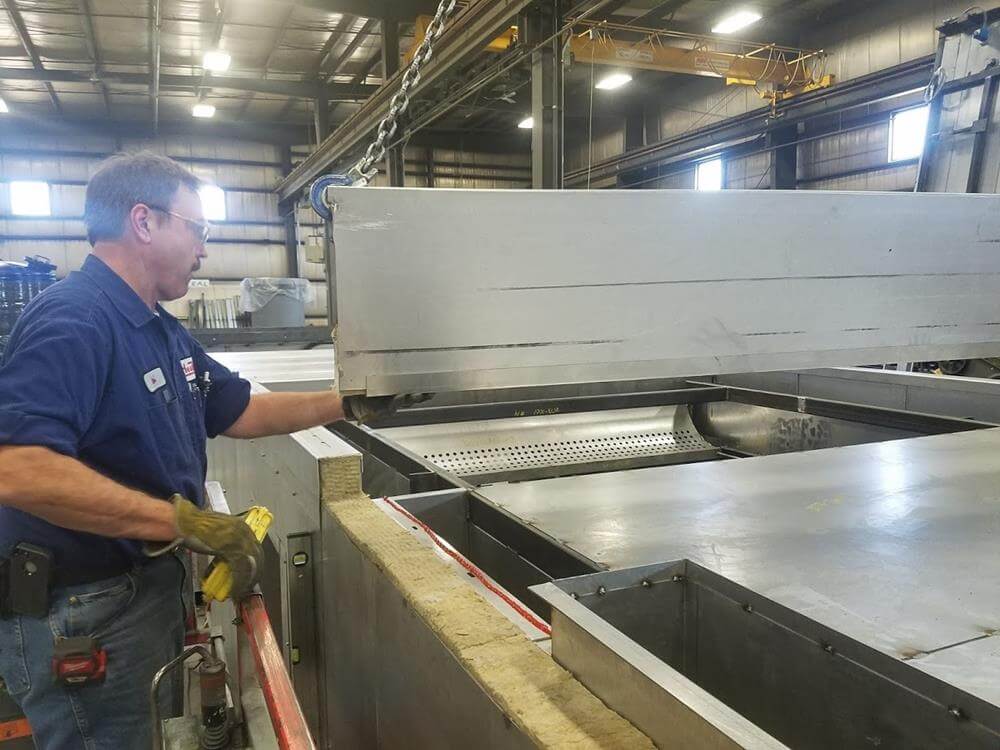
21. Install the roof panels starting at the heater box flashing. Be sure that the female joint is packed with insulation prior to inserting into the heater box flashing. The panels that are to be installed into the heater box flash have structural steel channels in the panels.
22. Pack the male end of the panels with insulation. (A cutting template has been provided so that the insulation strips can be precut)
23. Insert the next roof panel into the installed panel. Again, it’s best to hold the next panel at a slight angle to the installed panel and start the male end of the new panel into the female opening of the installed panel. Straighten or level the new panel in place. It is very important to maintain the correct panel gap. The insulated panel assembly drawing will show the “coverage” of each panel, which is the distance from female to female panel joints. When installed correctly, the gap, or reveal between the panels should be ¼’’ to 5/16’’.
24. Repeat for both sides of the heater box opening.
25. Once all of the roof panels are in place, pack the void between the roof and the wall panels.
26. Install the roof flashing. Seam weld the corners and where the flashing meets the heater box flashing.
27. Once complete, TEK screw the roof flashing in place.
28. Install the verticle heater box structure by welding it to the base flashing and roof flashing
29. Install the gasket (tadpole) onto the top of the heater box flashing. Hold in place with caulk.
30. Locate the heater box in place.
31. Fasten the heater box to the roof with supplied fasteners. The fasteners are self-threading, meaning a pilot hole must be drilled, and then, using an impact wrench and the supplied bolts, threads are formed in the buried structure. The holes will be drilled through the flashing, panel, and buried structural steel panel.
32. Locate and install the exhaust fan if equipped.
33. Install the bi-fold doors. Start by temporarily tack welding the supplied ½’’ spacer blocks evenly on both verticle flashings and the horizontal.
34. Install the external structural steel door frame. It is best to sub-assemble the frame and then level and attach the frame to the oven.
35. Install the door gaskets at the inside edge of the door flashing.
36. With a fork truck, position one of the doors in place against the ½’’ spacer blocks and mark the location of the holes in the hinges.
37. With a fork truck, position the second door in place against the ½’’ spacer blocks and mark the locations of the holes in the hinges.
38. Once again, the fasteners are self-threading, meaning a pilot hole must be drilled, and then, using an impact wrench and the supplied bolts, threads are formed in the buried structure.
39. Adjust the door gasket to the door.
40. Locate and mount the control panel.
41. Run conduit, pull wire, and terminate the wire to the terminal strip in the control panel.
42. Paint the oven.
43. Install Utilities
44. Burn the oven out and perform a safety check conforming to NFPA 86.
Commitment to Sustainability
Along with the world’s leading can makers, HeatTek understands and supports the importance of sustainable technology and net zero processes. Every detail is considered when engineering each of HeatTek’s Evolve Systems to ensure your sustainability goals are met or exceeded.
- Reduced gas usage through airflow and temperature optimization
- Minimized virgin water usage and chemical usage through RO technology
- Options for natural gas alternatives such as electric and infrared technology
- Recycled materials
- Consultations and audits for current system health and sustainability impact